


ADVANCED SIEVES AND PERFORATED SCREENSTESTING KIT
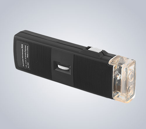
NOMINAL APERTURE CALIBRATOR WITH MAGNIFICATION OF 50X
Hand Microscope also known as a pocket microscope, is a device used to check the defects in wire mesh and perforation of sieves and screens. It consists of a LED light to illuminate the observing area and the eyepiece with an adjustable lens to zoom in or zoom out.
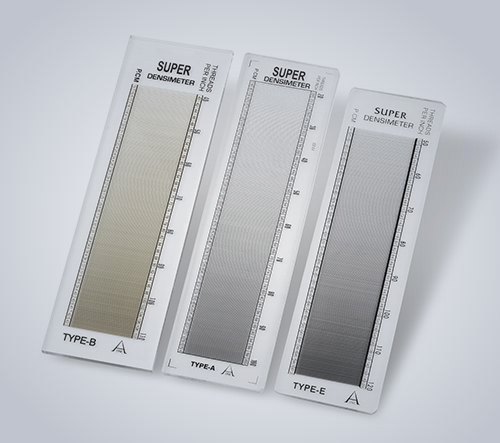
SCALES
In 1874, a Nobel Prize winner named Lord Rayleigh recorded graticular figures which occurred when superimposing very fine grids on top of each other. This optical phenomenon was later designated by the term Moire because of its watermarked effect. The densimeter is a commercial instrument made of artificial glass with etched in grating lines. By placing this instrument on a wire mesh surface, the lines of the instrument are coordinated with the structure of the wire mesh. Super positioning (“interference”) of the two grid systems will be observed. Since the grating of the instrument is one with linearly increasing grid constant, there must be somewhere in this “interference field”, a zone where there is complete harmony of both gratings (wire mesh and calibration lines) The scale beam provided on the side of the instrument, indicates the density value of the grating or wire mesh. The densimeter is used mainly to determine the thread density (set or thread count) on any wire mesh or knitted object having a parallel structure, e. g. a linen weave. For this purpose, the instrument is laid as parallel as possible to the thread (wire mesh) direction to be examined and on top of the sample. An interference pattern will appear immediately, taking the shape of an oval, complete pattern (in the case of parallel grid systems; in a hyperbolic form in the case of radial grid systems). The middle axis of the interference picture is important for an accurate reading of the thread count (number of picks) based on the instrument scales. The number of laterally running threads (warp threads) can also be ascertained in this manner, by slowly rotating the instrument, the Moire pattern changes and disappears almost completely at an angle of 45°. On further rotation up to 90° the Moire pattern will again emerge quite distinctly and will now relate to the laterally running threads. Measurements can be carried out in daylight without any artificial lighting.
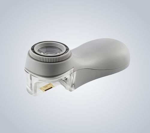
LINEAR MESH COUNTER WITH MAGNIFICATION OF 8X
The nominal aperture calibrator is an equipment also known as a Mobile Microscope.
PROCEDURE OF OPERATION:-
It is calibrated as, 1 interval is equal to 0.1mm, means 1 Interval is 100 Microns. This device is used to count the wire mesh opening and opening of mesh. Put the calibrated side on the wire mesh, look through the lens then count the number of openings within the scale's range. The scale is calibrated with 0.1 mm least count, and one division on the scale depicts 100 microns. If we get 8.4 divisions on scale within one opening of wire mesh, it shows that the wire mesh is of 840 microns which when converted through the table gives us 20#.
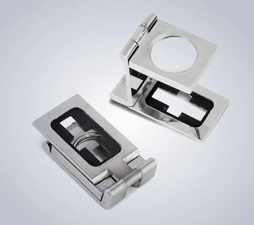
LINER MESH COUNTER WITH MAGNIFICATION OF 8X
Linear mesh counter or ‘PIC Gauge’ is used to measure wire mesh. Mesh number is determined as number of openings per linear inch. For example, let's discuss about 40#, it is 40 opening in one linear inch. The LMC is having Magnification of 8X. The figure below shows a simple 'Linear mesh counter'.
PROCEDURE OF OPERATION:
The glass or gauge consists of two surfaces on which one side is of magnifying glass and the opposite side is of calibrated scale. To inspect the wire mesh, place the calibrated scale on wire mesh surface as shown in the below figure.
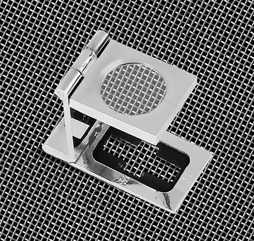 The calibrated scale must be in line or parallel with the wire. Observe the mesh through the glass and count the opening of one linear inch. For counting the wire mesh finer than 40#, then the openings must be counted on 1/4 inch scale than multiply the number of opening by 4 to get the exact mesh size per linear inch. The smallest section on the linear mesh counter is the 1/8th scale and this can be used for counting meshes finer than 60#. To calculate this, count the number of openings in the smallest section then multiply the counted openings with 8 to get the wire mesh count per linear inch.
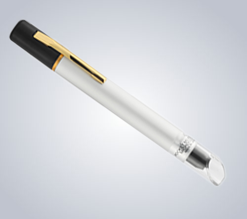
PRECISION PEN MICROSCOPE LEAST COUNT - 20 MICRONS
Pen microscope is a fountain pen type microscope. Bright and sharp images are available from every model, the magnification of which varies from 25X to 100X of which most frequent model is 25X and 50X Pen microscope is used to measure microns opening, opening of mesh. Put the microscope on a wire mesh and measure each scale between two wires, (Open area). Suppose you are using a 50X microscope, then count the number of lines between two wires. Suppose you are using a 50X model minimum scaled division is 0.02 mm means one line is 0.02 mm. As 1 mm is 1000 microns, so one line is 20 microns. Suppose you are using 60 mesh size and you got 12.5 lines which means 12.5 x 20 microns that is 250 microns is the opening of 60 mesh.
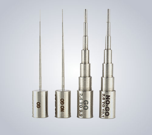
Go. No-Go GAUGE
Go. No-Go Gauge is a convenient way of measuring perforated sheets (Only Perforated Sheet). It has four measuring sticks with different steps and two Nylon threaded storage round boxes. Our standard Go. No-Go Gauge comes with four measuring sticks. Ranging to measure the perforated sizes from 0.5 mm to 10.0 mm. 0.5 mm, 1.0 mm, 1.5 mm, 1.8 mm, 2.0 mm, 2.2 mm, 2.5 mm, 3.0 mm, 4.0 mm, 6.0 mm, 8.0 mm and 10.0 mm. The client can choose their variation of sizes as per their requirement. Suppose the client wants to measure 0.5 mm. They have to insert the Go-Gauge where the first step is 0.4 mm and then No-Go Gauge. Where the first step is 0.6 mm. If the first step goes into the perforation sheet means the perforated sheet is bigger than 0.4 mm and when the first step of No-Go does not go inside the perforated sheet means the perforated size is smaller than 0.6 mm. assuming it as 0.5 mm.
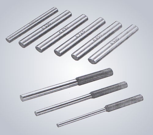
PRECISION MEASURING PINS SET OF 4 PC
The PIN GAUGE is the pin shape fixed size precisely cut cylindrical bars, comes in various sizes. The primary purpose of PIN GAUGE is to measure and inspect the diameter of small holes; it also can be used as a test bar for geometric deviations measurements.
LINER MESH COUNTER WITH MAGNIFICATION OF 8X
Linear mesh counter or ‘PIC Gauge’ is used to measure wire mesh. Mesh number is determined as number of openings per linear inch. For example, let's discuss about 40#, it is 40 opening in one linear inch. The LMC is having Magnification of 8X. The figure below shows a simple 'Linear mesh counter'.
PROCEDURE OF OPERATION:
The glass or gauge consists of two surfaces on which one side is of magnifying glass and the opposite side is of calibrated scale.
To inspect the wire mesh, place the calibrated scale on wire mesh surface as shown in bellow figer.
GO. NO. GO GAUGE
Go. No. Go Gauge is a convenient way of measuring perforated sheets (Only Perforated Sheet). It has four measuring stainless steel 316 L quality sticks with different steps and 02 Nylon threaded storage round box. Our standard Go-No-Go Gauge comes with 04 measuring stick. Ranging to measure the perforated size from 0.5 mm to 10.0 mm. 0.5 mm, 1.0 mm, 1.5 mm, 1.8 mm, 2.0 mm, 2.2 mm, 2.5 mm, 3.0 mm, 4.0 mm, 6.0 mm, 8.0 mm and 10.0 mm. The client can choose their variation of sizes as per their requirement. Suppose the client wants to measure 0.5 mm. They have 15 insert the Go-Gauge where the first step is 0.4 mm and then No. Go Gauge. Where the first step is 0.6 mm. If the first step goes into the perforation sheet means the perforated sheet is bigger than 0.4 mm and when the first step of No-Go does not go inside the perforated sheet means the perforated size is smaller than 0.6 mm. assuming it as 0.5 mm.
SCALES
In 1874, a noble prize winner named Lord Rayleigh recorded graticular figures which occurred when superimposing very fine grids on top of each other. This optical phenomenon was later designated by the term moire because of its watermarked effect. The densimeter is a commercial instrument made of artificial glass with etched in grating lines. By placing this instrument on a wire mesh surface, the lines of the instrument are coordinated with the structure of the wire mesh. Super positioning (“interference”) of the two grid systems will be observed. Since the grating of the instrument is one with linearly increasing grid constant, there must be somewhere in this “interference field”, a zone where there is complete harmony of both gratings (wire mesh and calibration lines) The scale beam provided on the side of the instrument, indicates the density value of the grating or wire mesh. The densimeter is used mainly to determine the thread density (set or thread count) on any wire mesh or knitted object having a parallel structure, e. g. a linen weave. For this purpose, the instrument is laid as parallel as possible to the thread (wire mesh) direction to be examined and on top of the sample. An interference pattern will appear immediately, taking the shape of an oval, complete pattern (in the case of parallel grid systems; in a hyperbolic form in the case of radial grid systems). The middle axis of the interference picture is important for an accurate reading of the thread count (number of picks) based on the instrument scales. The number of laterally running threads (warp threads) can also be ascertained in this manner, by slowly rotating the instrument, the moire pattern changes and disappears almost completely at an angle of 45°. On further rotation up to 90° the moire pattern will again emerge quite distinctly and will now relate to the laterally running threads. Measurements can be carried out in daylight without any artificial lighting.

Project Management
We are working in the format of an outsourcing project office. We assume operational coordination.

Support Functions
Integrating of innovation and public benefit into your workflows; ensuring strategic and sustainable.

Finance Planning
We identify the mission, goals and strategic priorities of a business project or non-profit organization.


